Reserve a pilot slot

Fold flat. Land anywhere. Live, farm or host guests by the next sunrise.

折M01–M04 Systems · Structure

A crease that seals, stops and locks itself.

Four mechanisms carry every ORIJO room: a hinge that is also the wall, a vault that unfolds on one degree of freedom, legs that turn land into a lease, and a tatami-sized socket that every organ plugs into. Below, each one is a working model — move it, take it apart, read the numbers it produces.

80 mm FRP / PIR facetsLatch every 910 mm26.5 m² per YOSHI-43 rooms per 40 ft HCDatum ≤ 0.5 mm target
力00 One load path, four mechanisms

Snow and wind travel from facet to soil through parts you can pick up and inspect on this page. Locks — not actuators — carry service loads.

  1. 01Snow, wind, self-weightFolded-plate shell action along ridges and valleysM02
  2. 02KASANE creaseCloseouts bear in compression; the latch takes the tension sideM01
  3. 03Haunch shoe → sill railStainless shoe on PTFE slide; ties across the span resist spreadM02
  4. 04MUTOIS floor diaphragm3.64 × 7.28 m cassettes with a sill beam each sideM02
  5. 05ASHI legJack trims level; pin lock holds height; X-brace takes shearM03
  6. 06Screw pileNo trench, no pour; unscrews when the lease endsM03
  7. +JO-PORT tilesOrgans dock on the floor diaphragm: datum, water, DC, dataM04
折M01 KASANE hinge

Two membranes and a gasket replace the taped seam.

Two membranes and a gasket replace taped seams: a tight membrane on the axis face of each crease and a slack bellows on the face that opens carry air, rain and vapour across the fold, a structural edge closeout takes bearing, and a thermally broken latch carries the tension side of the crease moment.

M01 EXPERIMENTAL
Fig. 01 · M01 KASANECrease section, 1.4 m long
Rain on the axis faceRoom vapourLatch state

Drag to orbit · click any part · click, then scroll to zoom

Facet thickness t
Dihedral, axis face model
204.0°

Stop at 204° — closeouts meet, the crease cannot over-rotate.

Axis-face membrane strain model
0.00%

The tight membrane sits on the rotation axis, so its length never changes.

Opening-face gap t·Δθ model
0mm

Bellows fitted: 150 mm (≥ 1.2·t·Δθmax).

Gasket compression target 30–40 %
35%

EPDM bulb, second air barrier, squeezed by latch preload.

Latch calculated
Engaged

T = M / 0.8t = 7.1 kN per latch at an illustrative 0.5 kN·m/m crease moment.

How the crease works

  1. 01

    At each crease the rotation axis sits on one face, and that face alternates between mountain and valley creases. A tight vacuum-laminated PVDF-coated polyester membrane spans the crease on the axis face. On the opposite face the edge gap changes by about t x dTheta, so the membrane there is a slack loop or bellows of at least 1.2 x t x dTheta (about 230 mm for t = 120 mm and a 90 degree fold change; about 150 mm for t = 80 mm), or a bonded EPDM or silicone strip with at least 300% elongation.

  2. 02

    Every panel edge carries a structural closeout of pultruded GFRP or hardwood, 15-25 mm deep. This closeout, not the core, is the bearing surface; a 10-20 mm aerogel strip sits behind it to keep the thermal line continuous.

  3. 03

    The offset or taper geometry lets each crease close only to its design dihedral; faces meet and stop it, so a wall cannot over-rotate even if a winch is mis-operated.

  4. 04

    At the design dihedral the edge closeouts bear on each other in compression. Under wind reversal the tension side of each crease moment passes through the latch, so the latch is a primary structural member: latch tension T is about M_crease / (0.8 t), and it is sized for fatigue as well as preload.

  5. 05

    The latch is thermally broken: a GFRP or polyamide body with a bronze cam only at the bearing point, mounted on the inside face behind the vapour layer so it does not pierce the membrane.

  6. 06

    An EPDM bulb gasket inside the membrane is compressed by the same latch preload as a second air barrier.

  7. 07

    Each latch carries a Hall-effect position sensor and a strain gauge; the module passport records engaged or not, and TSURU verifies every latch after deployment.

  8. 08

    A failed membrane or bellows strip is cut out over 300 mm and re-laminated with a field vacuum kit as an obi patch (target 30 minutes).

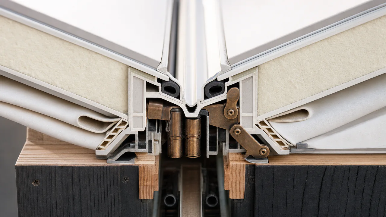
Macro section of a KASANE hinge: sandwich facets, closeouts, bulb gaskets, bronze cam latch and bellowsI02 · Hinge macro
I02Two 80 mm facets at the stop: membrane over the axis, slack bellows below, bronze cam on the inside face.Concept visual · AI

Why a bellows, not a tape

axis face · Δl = 0 opening face · Δl = t·Δθ t 80 mm × π/2 ≈ 126 mm → bellows ≥ 1.2 × 126 ≈ 150 mm

Key numbers

QuantityValueBasis
Deployment of thick panels on membrane-fold hinges (BYU ballistic barrier); weathertightness, insulation and cycle life unreporteddemonstrated (deployment only)measured
Edge gap change on the opening face of a creaseabout 125 (t = 80 mm) to 190 (t = 120 mm)mm per 90 degree fold changecalculated
Required bellows or slack-loop length on the opening faceabout 150 (t = 80 mm) / 230 (t = 120 mm)mmcalculated
Maximum facet strain during fold in kinematic simulation0 (rigid-foldable pattern required)%target
Latch tension per unit crease lengthT = M_crease / (0.8 t); e.g. 0.5 kN.m/m on t = 100 mm gives about 6.3 kN/m, or about 5.7 kN per latch at 910 mmkNcalculated
Panel areal mass, 120 mm PIR coreabout 10-12kg/m2calculated
Panel-centre U, 120 mm PIR (temperate only)about 0.18W/m2Kcalculated
Whole-wall U including creases and latches (polar)<= 0.15W/m2Ktarget
Envelope airtightness of 2 x 2 x 2 m test box and of the shell (same basis)q50 1.0-1.5m3/(h.m2) envelope at 50 Patarget
Fold-cycle life of membrane hinge and bellows2,000cyclestarget
Latch fatigue life at service wind load>= 1,000,000cyclestarget

Parts (also the non-WebGL view)

  1. M01.01Facet panelGlass-FRP faces, PIR core (mycelium optional), aerogel strip behind edge closeout80-120 mm temperate, 200-250 mm PIR-equivalent polar; 10-12 kg/m2 at 120 mm PIR (calculated)
  2. M01.02Edge closeoutPultruded GFRP channel or hardwood15-25 mm deep bearing surface; allowable bearing stress from closeout datasheet, not from the core (PIR about 0.15-0.3 MPa)
  3. M01.03Axis-face membranePVDF-coated polyester, vacuum laminatedtight across crease; target 2,000 fold cycles
  4. M01.04Opening-face bellowsSlack PVDF-polyester loop, or EPDM/silicone sheet (>= 300% elongation) bonded to membranelength >= 1.2 x t x dTheta (150 mm at 80 mm, 230 mm at 120 mm, 90 degree fold)
  5. M01.05Over-centre latchGFRP or polyamide body, bronze cam at bearing point only, stainless pinprimary tension member; T = M_crease / (0.8 t); 910 mm pitch; inside face behind vapour layer; Hall sensor
  6. M01.06Backup gasketEPDM bulbcompressed 30-40% at preload (target)
  7. M01.07Obi repair kitMembrane roll, adhesive, portable vacuum pump300 mm patch, 30 min (target)

EXPERIMENTAL: each ingredient is a prototype or lab result; the weathertight, insulated building hinge with an opening-face bellows is unbuilt and is the single most important risk in ORIJO.

宿M02 YOSHI vault

Two packs on a pad. One degree of freedom. A sealed room by evening.

Two road-legal half-shell packs, each 3.70 x 2.30 x 1.10 m, unfold on one degree of freedom into a 26.5 m2 insulated barrel vault of about 48 m3 whose creases are its ribs, its gutters and its robot rails.

M02 EXPERIMENTAL
Fig. 02 · M02 YOSHI-4Packs land on datum pins
Mountain creaseValley creaseLoad path

Scrub below · drag to orbit · click a part

Length model
0.80m
Span at sill model
2.87m
Rise model
1.81m
Haunch slide / side model
0mm
Max facet strain model
0.000%

Rigid-foldable: every panel keeps its shape.

Crease latches closed
0/ —

Model: graded Miura-derived cylinder, 14 × 18 panels per half, solved for a 3.64 m span and 3.64 m half-length; it reaches a 2.75 m rise against the 2.90 m brief. Zero-thickness kinematics — the Chen/You offset stack for 80 mm panels sets the real pack (3.70 × 2.30 × 1.10 m target, to be confirmed by fold simulation).

V01 · Atacama unfold
V01Gable portal winches out, the half-shell rises on one degree of freedom, haunch shoes slide along the sill rails.Concept video · AI

Expansion, exterior pack → interior room

YOSHI-4, shell only2.6×calculated
YOSHI-4, whole room2.2×calculated
TenFold TF-20, same basis1.9×calculated

48 m³ interior from 2 × (3.70 × 2.30 × 1.10) m packs; pack dimensions are a target until the Chen/You fold simulation confirms them.

Deployment, in order

  1. 01

    ASHI legs are set and levelled; MUTOIS floor cassettes unfold onto them to form a 3.64 x 7.28 m floor diaphragm with a sill beam on each long side.

  2. 02

    The shell ships as two half-length (3.64 m, 2-bay) packs. Each is lowered onto two kinematic datum pins, at the fixed gable for the first half and at the splice frame for the second; transit straps are released by app command after a pre-check.

  3. 03

    The moving gable portal is winched along floor rails. Because span and rise change as the cylinder extends, the haunch shoes run in PTFE-lined slides along the sill rails; the slide travel is designed, not left to friction. Near the folded state the pull force rises steeply, so the first part of the stroke uses a geared winch or a jack start, and counterweights (optional) balance the rising facets.

  4. 04

    At full extension the one-way offset stops engage; the two halves are joined at a latched splice ring frame; TSURU walks the ridge rail and closes each latch at 910 mm pitch, logging sensor state.

  5. 05

    Haunch facets lock into the sill shoe; tension ties across the span resist spreading thrust.

  6. 06

    A blower-door fan in the KURA core pressurises the shell; leaks are localised by TSURU thermal camera and fixed before handover.

  7. 07

    Load path: snow and self-weight travel as folded-plate shell action along ridges and valleys to haunch shoes, sill beams, ASHI legs and anchors; wind uplift returns through edge-closeout bearing, latches in tension and base ties. Retraction is the reverse.

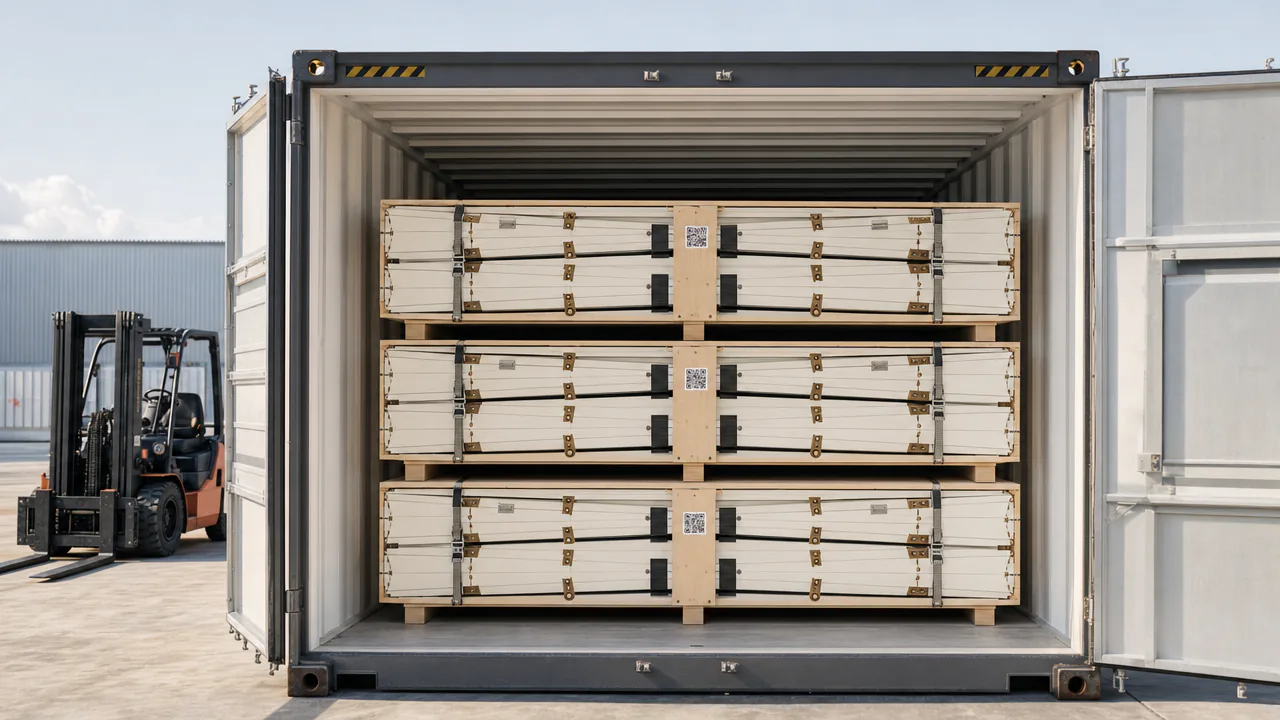
Six folded half-vault packs stacked two high in three positions inside an open 40 ft high-cube containerI03 · Flat pack
I03Six half-packs, three rooms, one 40 ft high-cube.Concept visual · AI

Key numbers

QuantityValueBasis
Floor area YOSHI-426.5m2calculated
Interior volume after shell thickness and inward corrugationabout 48m3calculated
Usable floor area at >= 2.1 m headroomabout 17-18m2calculated
Pack, 80 mm panels2 x (3.70 x 2.30 x 1.10) = 18.7m3target
Expansion ratio, shell only (exterior pack to interior deployed)about 2.6x volumecalculated
TenFold TF-20 on the same basis (exterior pack to interior deployed)about 1.9xcalculated
YOSHI-4 shipped per 40 ft HC container (80 mm panels)3roomscalculated
Mass YOSHI-4<= 2,200kgtarget
Crease length and verticesabout 300 m, dozens of degree-4 verticesmcalculated
Shell airtightnessq50 <= 1.5 (about 4 ACH50 at 48 m3 and about 130 m2 envelope)m3/(h.m2)target
Deploy time from packs on pad to sealed shell<= 4htarget
Parts list
  1. M02.01Facet setKASANE panels (M01), Chen/You offsetabout 87 m2 developed area for YOSHI-4 (calculated: arc about 8.5 m x 1.2 corrugation x 7.28 m x 1.2); panel solid volume 6.96 m3 at 80 mm, 10.4 m3 at 120 mm
  2. M02.02Gable portals and splice frameAluminium frame, hinoki infillabout 300 kg in total (estimate); winch mount
  3. M02.03Haunch shoe slideStainless shoe on PTFE-lined sill railtravel from fold simulation; friction coefficient <= 0.1 (target)
  4. M02.04Winch and optional counterweightsGeared 12 V winch; steel counterweight cassetteabout 300 kg if counterweights travel with the unit
  5. M02.05Floor cassettesMUTOIS aluminium-honeycomb modules2 x 4 ken, 2.5 kPa live load target
  6. M02.06Ridge railSegmented aluminium T-slot, socket bolted through to ridge beamdatum socket every 910 mm, broken at every transverse crease
  7. M02.07Base tiesDyneema or stainless rod with turnbuckleone per 1.82 m bay

EXPERIMENTAL: rigid-foldable thick-panel cylinders exist as models and small prototypes; an insulated, airtight, snow-loaded occupied vault is unbuilt.

地M03 ASHI legs

No pour, no trench. Six feet for six grounds.

Four to eight self-levelling legs on screw piles put a habitat on soil without a foundation pour or a trench, with a braced lateral load path; roof, snow, rock, water and regolith feet are concept-level options that each need their own structural case.

M03 COMMERCIAL
Fig. 03 · M03 ASHIScrew pile

Drag to orbit · click a part

Jack trim used
+60mm

Within the ±115 mm fine-trim band.

Floor level error
0mm

Pass: ±5 mm after trim target

Static load, this leg calculated
5.4kN

YOSHI-4, 21.6 kN on 4 legs; jacks rated 2–5 t.

Choose the foot

Wind case, YOSHI-4

What holds the room down when the wind turns.

Uplift and sliding set the anchor, not the weight. Move the design wind speed; every number is recomputed from the formulas in the brief: q = ½·1.25·V², U = q·0.8·26.5 m², B ≥ U/0.6 − D, H = q·0.8·21 m², N ≥ 1.5·H/μ with μ = 0.4.

Velocity pressure q calculated
1.00kPa
Uplift U calculated
21.2kN

vs dead load D = 21.6 kN

Ballast for uplift calculated
1.4t
Ballast for sliding calculated
4.8t

Why piles, not boxes, are the default foot.

Lateral per leg, 1.5·H/n calculated
6.3kN · 4 legs

3.2 kN with 8 legs; X-bracing or moment sill carries it.

On site

  1. 01

    Site scan by drone photogrammetry and a probe rod gives slope, soil class and obstacles; the configurator selects leg count, pile length and cut-off heights.

  2. 02

    Coarse slope is taken up by pile cut-off height or a stepped sill. Each telescoping leg then carries a jack for fine trim only: +/-115 to +/-230 mm (TenFold spec: 9 in total surface variability, hydraulic), which is about 3% (1.8 deg) over 7.28 m.

  3. 03

    Screw piles are driven by a compact excavator auger head (target 15 min per pile). No trench is dug.

  4. 04

    Lateral load goes through X-bracing between legs or a moment-rigid sill-to-leg connection. Each leg and pile head is rated for at least 1.5 x 1/n of the wind shear (about 5-10 kN per leg for 4-8 legs).

  5. 05

    Height is held by a mechanical pin or threaded lock nut with a published load rating. A separate replaceable impact absorber is fitted only where an impact case exists. Snow build-up and settlement are handled by re-jacking, as at Halley.

  6. 06

    HRV intake air is protected from frost without a trench: a glycol loop in thermal helical piles feeds a pre-heat coil, or an electric frost pre-heater (about 0.3-1 kW) sits on the HRV. A separate earth-tube trench is an option only for multi-year sites.

  7. 07

    Rooftops: zero penetrations only for HOSHI-class pods, subject to a structural check (even HOSHI-2 needs about 1-2 t of ballast). YOSHI-4 on an existing roof needs a spreader steel frame bearing on columns or beams, or mechanical tie-downs.

  8. 08

    To leave, legs retract, piles unscrew and the site is restored.

Key numbers

QuantityValueBasis
TenFold self-levelling range (hydraulic, 12 V DC)9 in (229 mm) total surface variabilitymanufacturer claimclaimed
Halley VI relocation (modules on hydraulic legs and skis)23km moved 2016-17measured
YOSHI-4 wind upliftabout 15-32kNcalculated
YOSHI-4 dead loadabout 21.6kNcalculated
Static load per leg, YOSHI-4 on 4 legsabout 5.4kNcalculated
Pile install time15min/piletarget
Parts list
  1. M03.01Telescoping legAluminium/steel tube with commercial jack (2-5 t rated)trim +/-115 to +/-230 mm; pin or lock-nut height lock
  2. M03.02Screw pileGalvanised helical pilepull-out and lateral capacity from site tests
  3. M03.03BracingSteel X-bracing or moment sill connection>= 5-10 kN lateral per leg (target)
  4. M03.04Impact absorber (optional)Replaceable crush cartridgeonly where an impact case exists
  5. M03.05Frost pre-heatThermal-pile glycol loop + coil, or electric HRV pre-heaterabout 100 W per 60 m3/h per 5 K; 0.3-1 kW
  6. M03.06Concept feet (not in prototype)Ballast pallet box with bagged sand / UHMW ski / stainless rock plate / HDPE pontoon / regolith bageach needs its own structural, buoyancy or mooring case

COMMERCIAL components (screw piles, jacks, bracing); EXPERIMENTAL as a levelled, braced leg system; SPECULATIVE for ski, pontoon, rock-plate, rooftop-ballast and regolith feet

守M04 JO-PORT

Every organ plugs in like a tatami mat.

A 910 x 1820 mm floor tile with a three-point datum spread over the module footprint and separate utility islands that every organ - water, battery, farm cassette, bath, bed - plugs into like a tatami mat, after a passport handshake and a leak test.

M04 EXPERIMENTAL
Fig. 04 · M04 JO-PORT910 × 1820 mm tile · MIZU-1 docking
PotableGreyDC 48 VData · NFC
Datum0/6
Leak test—
DC bus0 V

Drag to orbit · click a part

  1. 1ApproachThe organ is lowered by TSURU or rolled by two people. Its passport says MIZU-1, 170 kg, four ports.
  2. 2Lead-inBronze lead-in cones take out up to ±6 mm of placement error before any ball touches steel.
  3. 3Seat · 6 contactsThree hardened balls drop into three V-grooves: two flank contacts each, six constraints, zero redundancy. Weight goes to flat pads; a spring clamp preloads the seat.
  4. 4Passport handshakeNFC reads ID, revision, mass, ratings, ports and firmware; the controller checks them against the site configuration.
  5. 5Mate & leak-testFlat-face dry-break couplers mate. The closed space between them is pressurised and watched for decay before the solenoid valve opens.
  6. 6DC prechargeThe 48 V island precharges through a resistor, then closes. Any failure leaves only that island isolated.
  7. 7LivePotable in, grey out, power and data flowing. Urine never crosses a dry-break: it leaves by a gravity drain with an air gap.
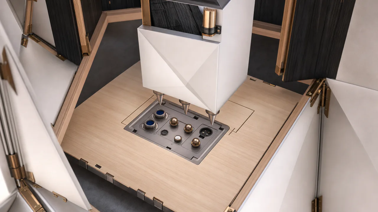
Hinoki floor tile with a recessed port box: datum balls, indigo water couplers, DC connector; a white appliance hovering above on lead-in conesI04 · Tatami socket
I04Port box with datum balls, separate water islands, DC and NFC.Concept visual · AI

Docking organ: Mizu water organ (WOTA-Unit class, partner) · 1.68 x 0.78 x 1.40 (fits 1 jo) m · 170 kg PILOT

Why the datum is spread, and why it is steel

Clustered at one end · rejected 4.5 mm Spread over the footprint · JO-PORT ≤ 0.5 mm
Contact stress, 25 mm steel ball on hardened V-block calculated
≈ 2.5–3GPa at 1.3 kN

Hertz: within a hardened insert's capacity (≥ 58 HRC).

Rejected: R10 bronze ball on cast aluminium calculated
≈ 1.8GPa

6–9× the yield of A356-T6 — it would dent on the first dock.

Key numbers

QuantityValueBasis
WOTA Unit: footprint inside a 1820 x 910 jo (65-70 mm margins), AC 115 V/60 Hz, 400 W rated, 170 kg dry, 450-720 L/day, under development for mass production1680 x 780mmclaimed
Hybrid AC/DC house efficiency gain, only while DC load < 1.5-2.0 kW; a 60 V bus extends the range4-11%modelled
Sekisui Heim HAPPS: parts picked per house from catalogue (2006)about 30,000 of about 300,000partsreported
Floor area cost of twin ports1.66m2 per critical organcalculated
Swap time of a 1-jo organ< 60 two-person (robot time only if TSURU available)mintarget
Datum repeatability after 500 cycles with ISO 12103-1 A4 coarse dust, measured at the far end of the module<= 0.5mmtarget

Parts

  1. M04.01Datum setHardened 52100 steel balls (>= 58 HRC), hardened steel V-block inserts, flat bearing padstwo balls at port end, one at far end; at 1.3 kN a 25 mm ball on hardened steel gives p0 about 2.5-3 GPa (calculated)
  2. M04.02Port boxCast aluminium on compliant float+/-3 mm float
  3. M04.03Water islandsStainless flat-face dry-break couplers (ISO 16028 class), solenoid isolation valve, test port, pressure transducerpotable and grey separated; urine by gravity drain
  4. M04.04DC islandBlind-mate connector (Anderson-class)2 kW per port; house DC total <= 2 kW at 48 V, or a 60 V bus; heavy loads (bath, heat pump) on 380 V DC or AC
  5. M04.05Edge keysLVL or steel1-2 mm clearance, wedge or cam take-up
  6. M04.06Passport tagNFC + QRlinks to fleet record

EXPERIMENTAL integration of COMMERCIAL parts (connectors, DC hardware); the water organ is a stand-in, because the WOTA Unit is PILOT (pre-mass-production, AC only, no port interface)

試12 mo Prototype programme

Each mechanism has a test, a pass line and a kill line.

The hinge comes first: the vault does not get tooled until a KASANE crease has survived 500 powered fold cycles. If a gate fails, the fallback is written down in advance.

M01

KASANE hinge

USD 70,000-150,000 including rigs, chamber rental and lab fees (materials only about 18,000-35,000)
Build
2.4 m thick-panel Miura wall section (Tachi tapered panels) and a 3.64 m span x 1.82 m long rigid-foldable quadrilateral-panel vault strip (Chen/You offset panels; pattern verified at zero facet strain), both with axis-face membranes, opening-face bellows, edge closeouts, thermally broken latches and gaskets; a 2 x 2 x 2 m sealed test box built from the same facets; hinge coupons for ageing.
Test
Water spray rig (EN 12865-style) on every opening-side crease; low-flow blower-door or duct-blaster test of the box (q50); 2,000 powered fold cycles on the full articles at ambient; UV and freeze-thaw ageing in parallel on hinge and bellows coupons (ISO 4892-2 / EN 12467-style blocks); latch tension and fatigue tests; hot-box or calibrated thermal-camera whole-wall U; sandbag uplift on the strip; fire screening by cone calorimeter (ISO 5660) on panel plus membrane laminate.
Pass
No water penetration in the spray sequence; box q50 <= 1.5 m3/(h.m2); membrane and bellows intact and leakage rise < 25% after 2,000 cycles; latch preload retained within 10%; coupons pass ageing blocks; cone-calorimeter results consistent with a target of Euroclass B-s2,d0 (EN 13501-1), with NFPA 285 as the US route.
Kill
Membrane delamination before 500 cycles, box q50 > 3.0 m3/(h.m2) with gasket, or water penetration at any opening-side crease (bellows): occupied enclosures revert to the v2 rule (fixed insulated rooms, origami only on unoccupied canopies and wings).
M02

YOSHI vault

USD 60,000-120,000
Build
Precondition: M01 hinge built and through at least 500 test cycles by month 4. Then one half-length (3.64 m, 2-bay) full-section YOSHI shell on a test pad with ASHI legs, gable portal, haunch slides and geared winch; temperate 80 mm panels; pattern verified at zero facet strain before tooling.
Test
Fold simulation vs measured pack envelope; 5 timed deploy/retract cycles with 2 people + TSURU v0; winch force and haunch-slide travel log; water-bladder roof load to 1.5x the pilot-site design snow load (ASCE 7-22 basis); wind uplift by bladder/winch rig; blower door (q50). Winter thermal logging and the 20-cycle wear test move to a month 12-18 gate on the full-length shell.
Pass
Measured pack within the 3.70 x 2.30 x 1.10 m envelope; half-shell deploys <= 4 h with no crane; deflection within FE prediction +/- 20%; q50 <= 1.5 m3/(h.m2) at month 12 (fallback <= 2.5).
Kill
Facets need > 25% extra mass for stiffness, deployment needs a crane, or leakage cannot be brought below q50 3.0 m3/(h.m2): freeze occupied YOSHI and sell F2/F3 wings and masts on fixed rooms.
M03

ASHI legs

USD 25,000-60,000
Build
Leg set with screw piles, jacks, pin locks and bracing for the M02 half-length test shell; electric HRV frost pre-heater; one rooftop-ballast feasibility calculation with a structural engineer, using commercial pallet boxes or bagged sand (no custom crate mould).
Test
Levelling accuracy on a graded slope with stepped sill; pile pull-out and lateral load tests; leg and bracing lateral test at 1.5x design shear; frost pre-heat performance in a cold chamber or winter site.
Pass
Level within +/- 5 mm after trim; pull-out >= 2x design uplift; lateral capacity per leg >= 1.5 x 1/n of design wind shear; HRV intake above -5 C (target) in local winter.
Kill
Screw piles cannot meet uplift plus lateral load at typical soils without concrete: switch to precast pad footings and keep the leg and jack system.
M04

JO-PORT

USD 35,000-60,000
Build
Six floor tiles with spread datums, floating port boxes and isolated fluid islands, plus three organs: a buildable DC greywater test organ (pump, filter, UV, tanks, 50-150 kg), a 10-15 kWh LiFePO4 rack and an NFT farm rack; DC precharge and protection electronics; test rig.
Test
500 mate/unmate cycles with ISO 12103-1 A4 coarse dust and mud; interstitial pressure-decay tests; electrical precharge faults; datum repeatability by CMM or dial-indicator rig at the far end of the module; two-person swap timing; urine-drain struvite run.
Pass
Zero leaks and zero unsafe enables in 500 cycles; datum repeatability <= 0.5 mm at the far end after 500 dusty cycles; swap < 60 min by two people; robot swap timing only if TSURU is available.
Kill
> 1% false mates or seal damage from dirt: split the port into a datum tile plus a separate hand-connected utility panel.

Known risks

M01 KASANE hinge

  • UV and abrasion ageing of the coated fabric and bellows at outside creases
  • Ice formation in valley drainage channels and condensation at crease lines in cold climates
  • Fire performance of FRP and foam cores (no code route proven yet)
  • Thermal bridging at latches and edge closeouts
  • Latch fatigue under wind reversal
  • PFAS regulation of fluoropolymer coatings

M02 YOSHI vault

  • Snow drift on crease valleys creating unbalanced loads
  • Tolerance stack-up across about 300 m of crease and dozens of vertices
  • Haunch slide friction and peak winch force near the folded state
  • Pack envelope not yet confirmed by fold simulation
  • Code approval of a novel folded shell
  • Hinge wear during repeated relocations

M03 ASHI legs

  • Frost heave on piles
  • Low lateral capacity of helical piles in soft soil
  • Wind sliding on roofs and roof structural capacity under ballast
  • Trench safety and excavation cost where an earth tube is chosen
  • Biofouling, fitting corrosion, permitting of open-water heat exchange, mooring and stability for the pontoon foot
  • Custom crate tooling (about USD 50-150k mould) if a jo crate is ever made

M04 JO-PORT

  • Dirt and ice in couplers
  • Struvite and calcium scale fouling in urine lines
  • House DC load above about 2 kW erasing the 48 V DC advantage
  • Standardising before the catalogue is stable
  • DC arc-fault protection maturity
  • WOTA Unit availability outside Japan and pilot regions
Sources for M01–M04